Product Details:
|
|
Brand Name: | GE |
---|---|
Model Number: | DASH3000 4000 5000 |
Payment & Shipping Terms:
|
|
Minimum Order Quantity: | 1 |
Price: | Negotation |
Packaging Details: | Carton Packing |
Delivery Time: | 1-3 Working Days |
Payment Terms: | T/T, Western Union, PayPal |
Supply Ability: | 1-20 Pieces |
Detail Information |
|||
Warranty: | 90 Days | Quantity: | Excellent |
---|---|---|---|
Stock: | Ex-stock | Lead Time: | 1-3 Work Days After Payment |
Package Details: | Normal Standard Package | Application: | Patient Monitor |
Payments: | TT/Western Union Or Paypal | Meterial: | Plastic |
Product Description
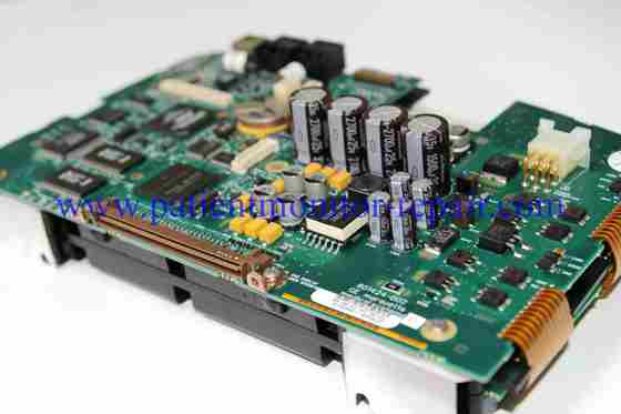
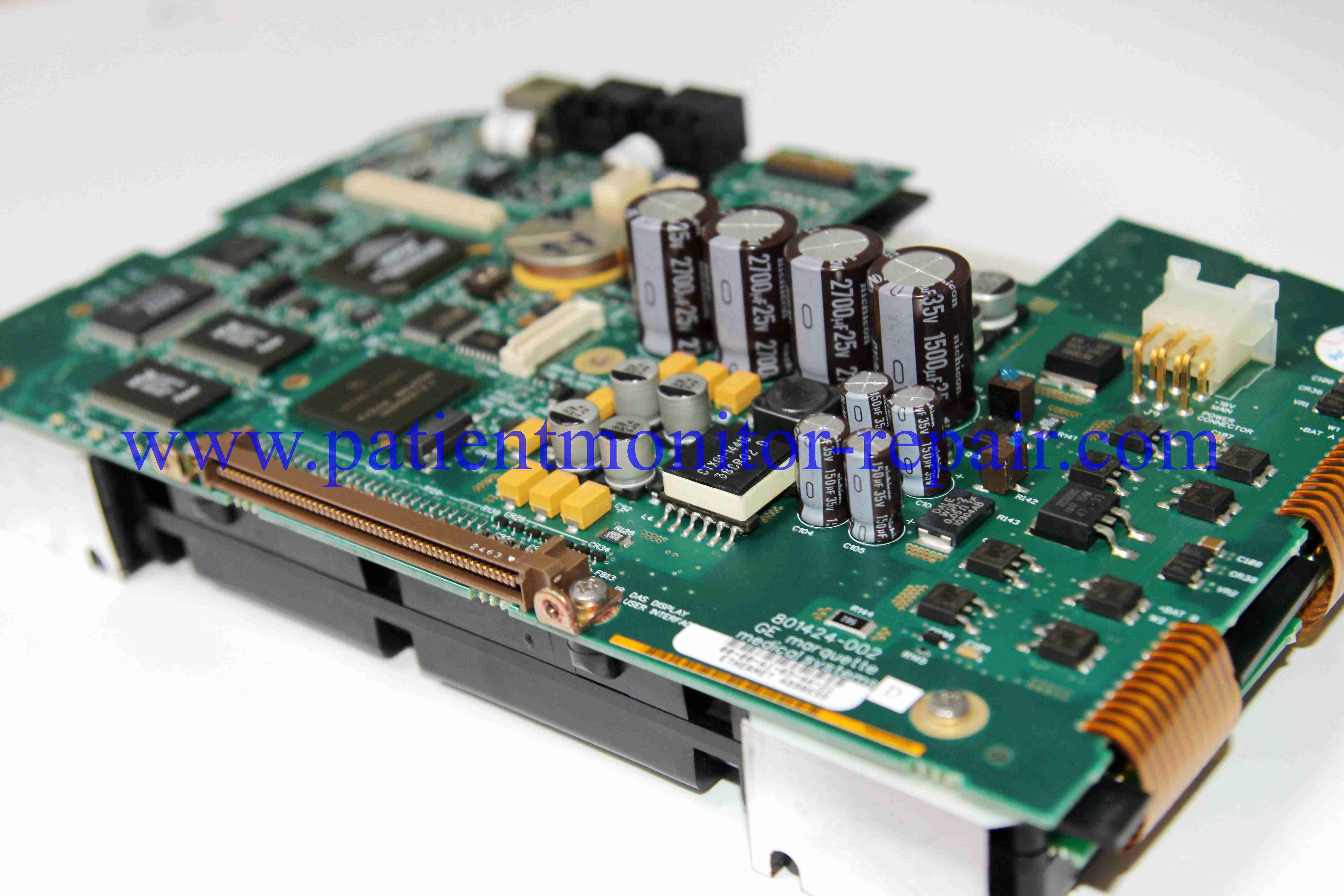
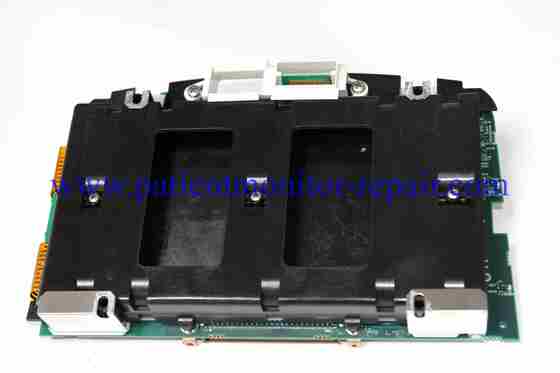
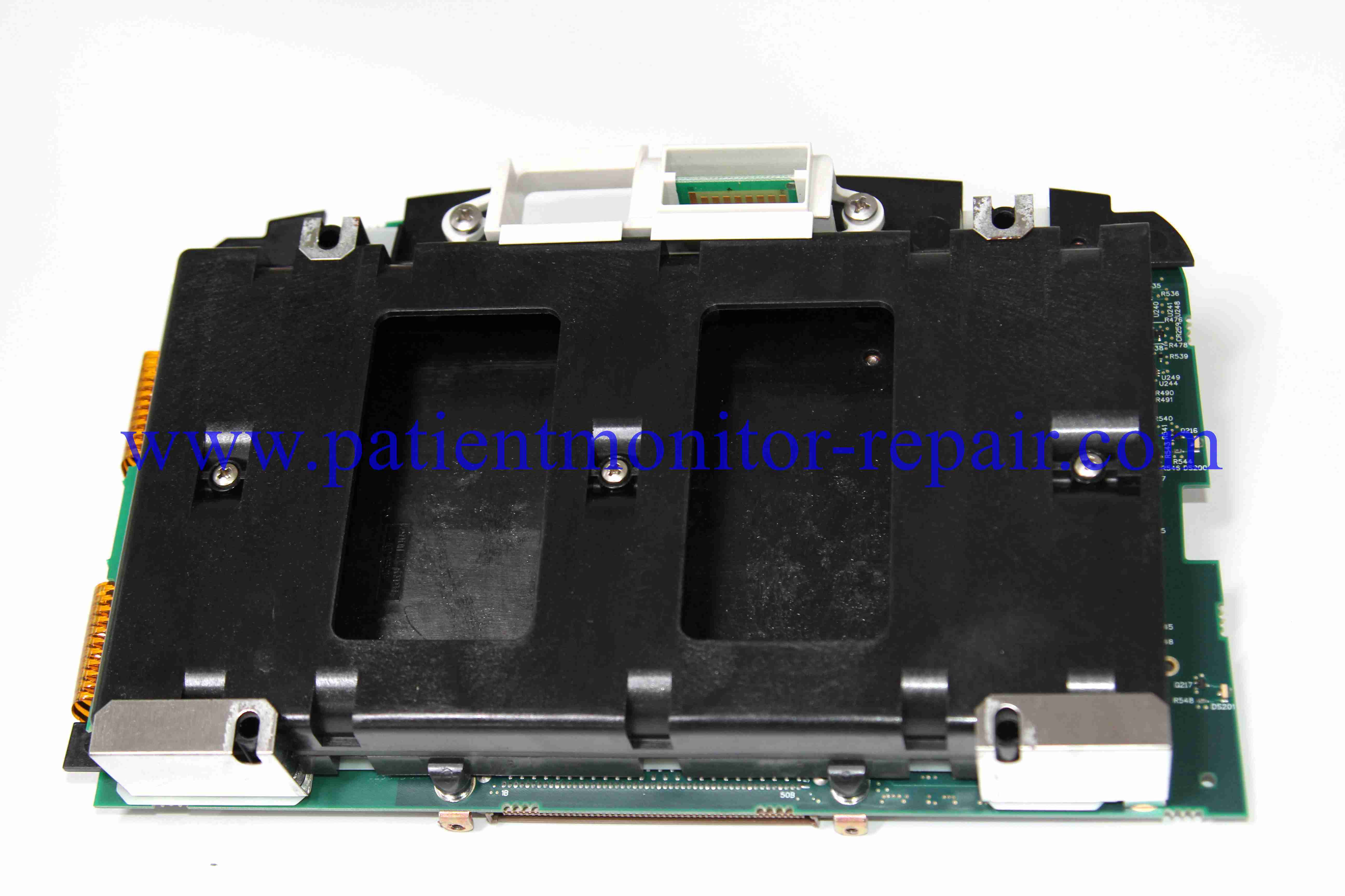
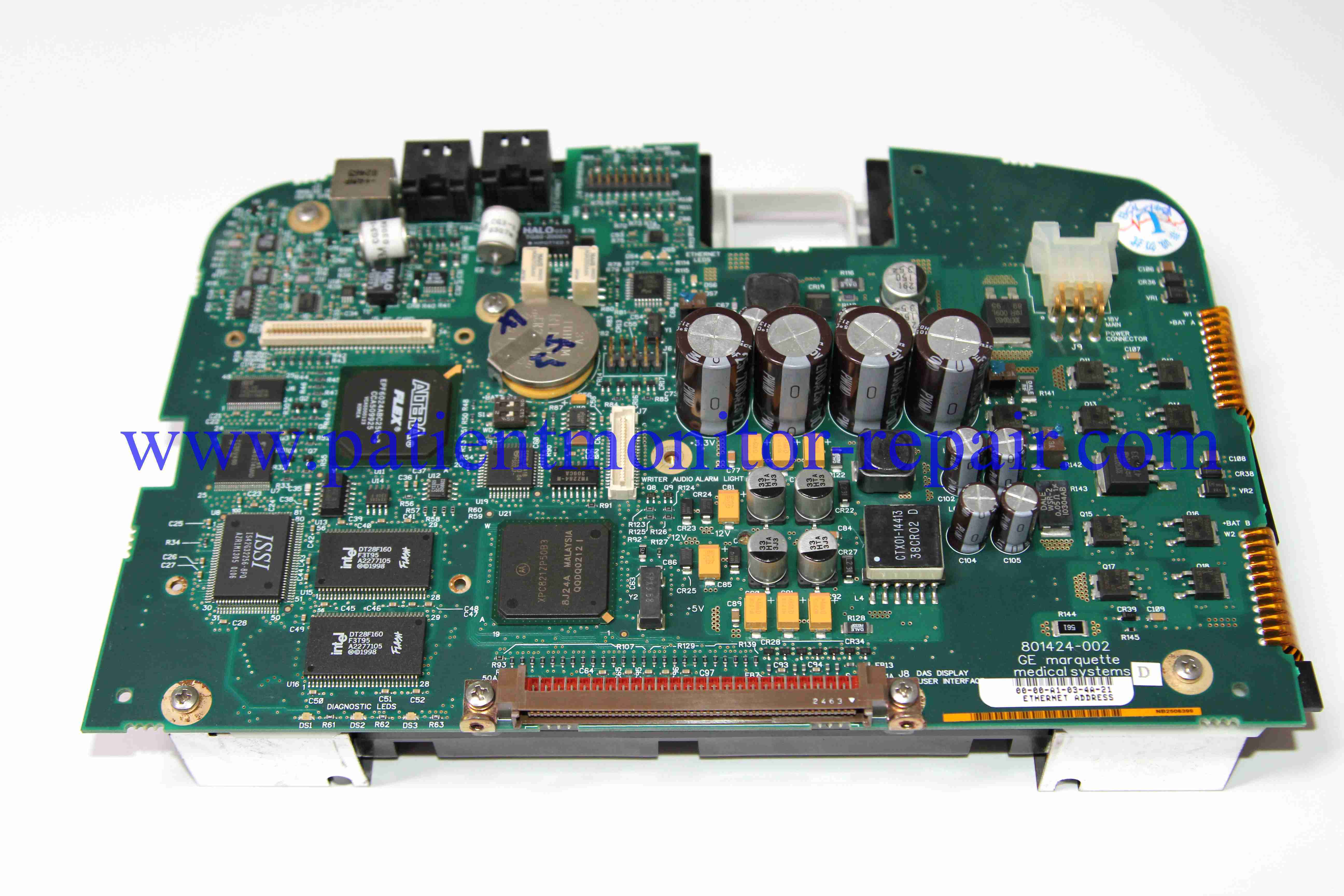
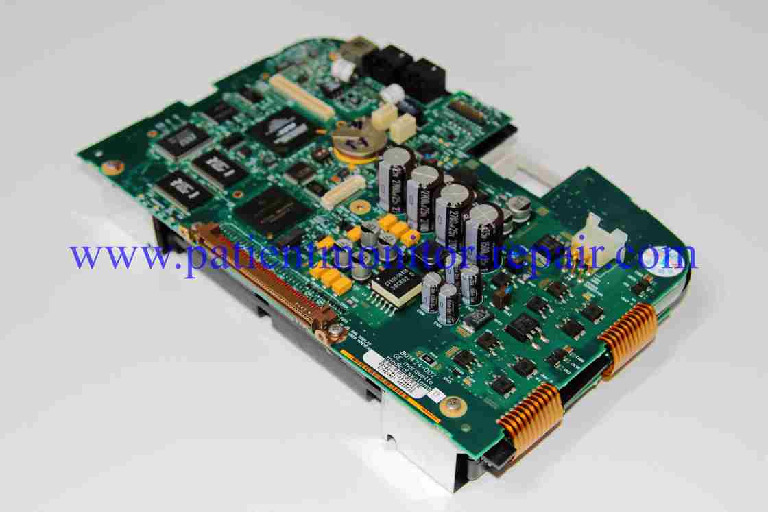
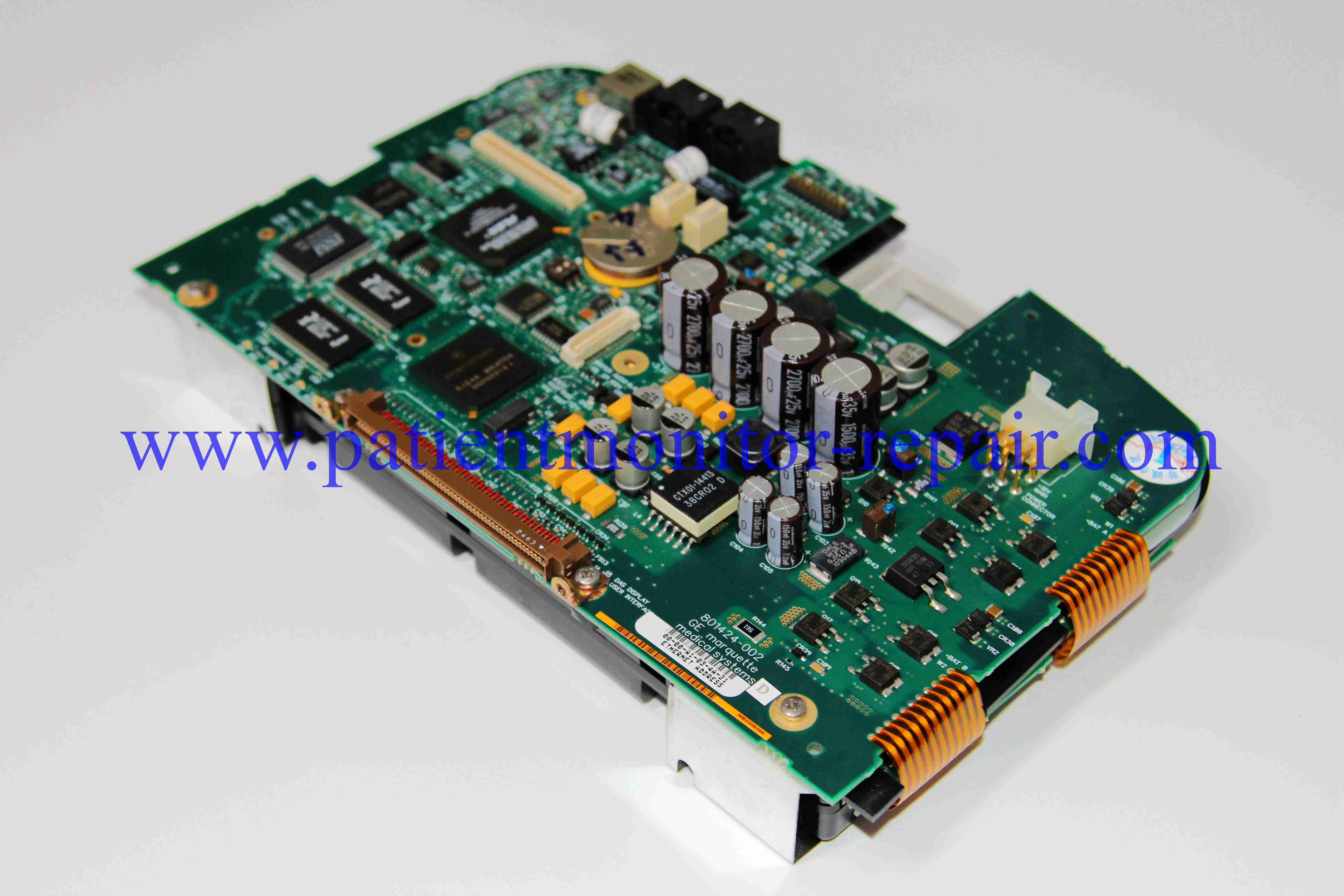
Here is a point-by-point guide on how to use the GE DASH 3000/4000/5000 patient monitor motherboard, intended for qualified biomedical equipment technicians (BMETs).
Important Disclaimer: The motherboard is the core internal component. "Using" it refers to procedures for installation, testing, and troubleshooting by trained technicians. This is not a guide for clinical use by healthcare providers.
Verify Model Compatibility: Confirm the replacement motherboard is explicitly compatible with your specific DASH model (3000, 4000, or 5000) and its exact hardware configuration. A board for a DASH 5000 may not work in a DASH 3000 and vice versa.
Power Down and Disconnect: Completely power off the patient monitor. Disconnect it from AC mains power and remove the monitor from the wall mount or pole. Remove the main battery pack.
Electrostatic Discharge (ESD) Protection: Mandatory. Always wear a properly grounded anti-static wrist strap and work on an ESD-safe mat. The motherboard contains highly sensitive BGA chips and components极易受损 by static electricity.
Prepare the Environment: Work in a clean, well-lit, and static-free area to avoid contamination or physical damage to the board.
Gather Tools and Documentation: Have the necessary tools (e.g., Torx screwdrivers, spudgers) and, critically, the official GE Service Manual for your specific DASH model. The disassembly process is complex and requires precise guidance.
Disassemble the Monitor: Follow the service manual's exact steps to remove the outer housing, front bezel, and display assembly to gain access to the internal components. This process is intricate and involves multiple steps and cables.
Document Connections: Before disconnecting anything, take high-resolution photographs and create diagrams of all ribbon cables, wire harnesses, and connectors attached to the existing motherboard. Note the orientation of all ribbon cables. Misconnecting these is a primary cause of failure.
Disconnect Cables: Gently disconnect all cables from the old motherboard. Many connectors have ZIF (Zero Insertion Force) locks or latches that must be carefully flipped up before the cable can be removed.
Unscrew and Remove: Unscrew the motherboard from its mounting standoffs. Carefully lift the board straight up and out of the chassis, avoiding any contact with other components.
Inspect the New Board: Visually inspect the new motherboard for any signs of physical damage, bent pins, or damaged connectors incurred during shipping.
Position and Secure: Align the new motherboard correctly with the mounting holes. Carefully lower it into place and secure it with the correct screws. Avoid any flexing of the board.
Reconnect Cables: Using your pre-documentation (photos/diagrams), methodically reconnect all cables and wiring harnesses to their exact locations on the new motherboard.
Ensure every connector is firmly and fully seated.
Crucially, remember to re-engage the ZIF locks on the ribbon cable connectors after insertion. A loose ribbon cable will cause a display or touchscreen failure.
Reassemble the Monitor: Carefully reverse the disassembly process to put the monitor back together. Ensure all components are aligned correctly and all screws are tightened to the specified torque.
Initial Power On: Reinsert the battery and connect the monitor to AC power. Power the unit on.
Observe Start-Up: The device will perform an extended self-test. Observe for any error codes (e.g., FPGA, DSP, or Memory errors) that indicate an improper installation or faulty board.
Enter Service Mode: You will need to access the hidden Service Mode to complete the installation. This typically involves a specific key sequence on startup (detailed in the service manual).
Calibrate the Touchscreen: A critical step. Use the calibration utility within Service Mode to accurately calibrate the touchscreen. An uncalibrated touchscreen will be unusable.
Verify Hardware Configuration: The motherboard may need to be configured in Service Mode to match the monitor's specific hardware options (e.g., installed parameter modules).
Perform Comprehensive Functional Tests: Test every parameter and function:
Display & Touch: Verify clarity and calibration.
ECG, SpO₂, NIBP: Use a patient simulator to verify waveform quality and numerical accuracy.
Alarms: Test all alarm functionalities.
Network & Interfaces: Verify Ethernet and serial port functionality if applicable.
Clear Error Logs: Use Service Mode to clear any historical error logs from the previous motherboard.
Record the Service: Meticulously document the entire procedure in the device's service history log. Include the date, reason for replacement, old and new motherboard part numbers, and the results of all tests and calibrations.
Regulatory Compliance: This repair must be performed in accordance with GE's specifications and relevant medical device regulations (e.g., FDA, CFDA) to maintain the device's compliance and safety for clinical use.
Final Warning: This is a complex procedure for highly qualified personnel only. The DASH monitors have a tightly integrated design. Incorrect installation can permanently damage the new motherboard or other components, leading to costly repairs and rendering the life-support device unsafe for patient use.
Enter Your Message